Abstract: For successful hardware design, it is best to evaluate specific applications before selecting serializer / deserializer (SerDes) components. The design guide provided in this application note helps to quickly configure the I²C mode of the MAX9257 / MAX9258 EV kit to display the graphical user interface (GUI) changes step by step. According to these instructions, I²C mode configuration can be completed quickly.
The following content provides an in-depth introduction to all the functional and feature tests of the MAX9257 / MAX9258 evaluation board. As a special example, I²C mode was selected. Before configuring this mode, power on the evaluation board as usual and start the software. This application note assumes that users have mastered and are familiar with the use of the MAX9257 / MAX9258 evaluation board. Note that the MAX9257 / MAX9258 evaluation board information requires an application to obtain it.
Make sure all jumpers are in the default position, as shown in Table 1.
Table 1. MAX9257 / MAX9258 EV kit jumper settings
Connect a 5V power supply between the 5V and GND pads on both layers of the evaluation board (Figure 1). Do not turn on the power until all connections are completed and all jumpers are correctly positioned.
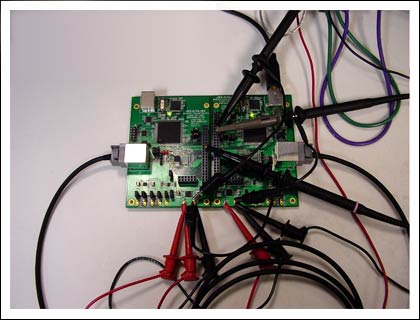
Figure 1. Configuration settings for experimental testing
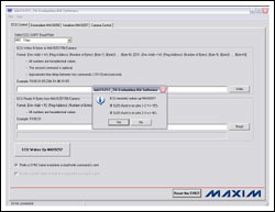
Connect the JAE cable between J2 and J7. Connect CH1 of the oscilloscope to J1-37. Connect CH2 of the oscilloscope to J1-35. Connect CH3 of the oscilloscope to J5-12. Connect the USB cable between the PC and J3 (note: not J8). In the Start menu, open its icon to start the MAX9257_58 evaluation software. When the "if ECU remotely wakes up the MAX9257" menu pops up, click the Yes button. The main software window shown in Figure 2 appears.
Detailed pictures (PDF)
Figure 2. The main software window that appears when the Yes button is clicked indicates that the MAX9257 is waked up remotely by the ECU. Once the ECU wakes up the MAX9257, TxIN, RxOUT and CCEN are all high.
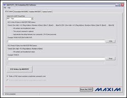
Make sure that the "EV kit connected" message is displayed in the status bar of the main window of the software, indicating that the evaluation board is connected correctly. Click the ECU Wakes Up MAX9257 button on the ECU Control page (Figure 3).
Detailed pictures (PDF)
Figure 3. Click the ECU Wakes Up MAX9257 button
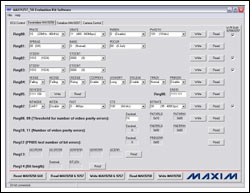
Click the Deserializer MAX9258 tab to jump to the Deserializer MAX9258 page (Figure 4).
Detailed pictures (PDF)
Figure 4. Jump to the Deserializer MAX9258 page
Click the Read MAX9258 & 9257 button to read the MAX9258 and MAX9257 registers. Select the ETOCNT drop-down menu and click the Write button to the right of Reg03 to set MAX9258 register 03 ETOCNT and MAX9257 register 03 ETOCNT to 0100. Set the MAX9258 register 07 CTO and MAX9257 register 08 CTO to 111 by selecting the CTO drop-down menu and clicking the Write button to the right of Reg07. Click the Serializer MAX9257 tab to jump to the Serializer MAX9257 page. Select the SEREN pull-down menu and click the Write button to the right of Reg04 to enable the MAX9257 SEREN bit. Note that when there is data communication on the link, the SEREN window should always be active. Click the Camera Control tab to jump to the Camera Control page. Click the Slow Blink D4 button; make sure the LED D4 flashes for about 5 seconds. Click the Enable PCLK_IN / HSYNC_IN / VSYNC_IN button; make sure that the LOCK indicator LED D1 is turned on. If it is on, the system is locked. Use a multi-track oscilloscope to check the board waveform. Set the corresponding trigger, you can observe the link's sending / receiving process and the transmitted data. After verifying the general functionality of the board, you can follow the steps below to put the evaluation board into I²C mode. I²C is a required mode that allows users to maintain control of all control registers and their contents.
If the camera has an I²C interface, both the MAX9258 and MAX9257 should be configured for I²C interface operation. Since the on-board emulated camera works on the default UART interface, the camera should first switch from the UART interface to the I²C interface. Follow the steps below to use the I²C interface of the evaluation board.
Start the program or click the Reset the EVKIT button on the ECU Control page. If MAX9257 REM is set high (JU25 1-2 pins are equipped with a shunt), click the ECU Wakes Up MAX9257 button on the ECU Control page. If MAX9257 REM is set to low level (JU25 2-3 pin is equipped with a shunt), skip this step. Jump to the Deserializer MAX9258 page. Click the Read MAX9258 & 9257 button to refresh the GUI's current register value, and the most recent register value (or the default value at startup) will be displayed. Select the 4 check boxes under the W / R Both 9258 & 9257 label, and the SerDes register can be set at the same time, so that users can avoid contradictions in the SerDes parameter settings. Set the MAX9258 and MAX9257's tCTO to 64 bits (CTO = 100). Jump to the Camera Control page; click the Exit UART Mode-> Enter I²C Mode button. Follow the information prompts-change the short-circuiter from pins 1-2 of JU26 / JU27 to pins 2-3, and click the OK button. Now, the camera and SerDes have adopted I²C interface to work. You can verify that the camera is working properly by testing the on / off and fast / slow blinking of the D4 diode. The control button for this function is located on the left side of the form. You can jump to any page and use this function of SerDes (ie, rewrite to each accessible register). When simulating the I²C interface of a camera, the operating speed is as high as 4.25MHz, as is the MAX9258 and MAX9257. Before changing the ECU I²C master clock, the BITRATE register bits of the MAX9258 and MAX9257 should be correctly configured. If data is transmitted on the link, make sure that SEREN is set to Enabled. Test instruments and components required to verify the performance of the MAX9257 / MAX9258 evaluation board Hewlett-Packard E3620A: dual 0 to 25V, 0 to 1A power supply. Tektronix TDS 3014: 4-channel DSO, 100MHz BW, 1.25Gsps sampling rate and standard 10x probe. PC or laptop based on Windows® XP, supports USB interface. 2m JAE cable (effective connection between the MAX9257 serializer and MAX9258 deserializer) I²C communication mode of the MAX9257 / MAX9258 evaluation board This test procedure describes the steps for the evaluation board to communicate in I²C mode. For this mode to work properly or set correctly, the system must first be started in UART interface mode. Setting MAX9257 / MAX9258 requires software to set INTMODE = I²C (make sure to check the option box on the right side of the screen to update / write to MAX9257 and MAX9258). To write to the device, trigger the TxIN pin once to collect the command sequence written to the device (ie, to establish the I²C mode setting). The board shown in Figure 5 is configured to send (TxIN, CH2) and receive (RxIN, CH3) data in the limited CTO mode, which is required when configuring the board for I²C mode. Note that all steps are performed in UART mode (JU26 and JU27 pins 1-2 are equipped with a shunt).
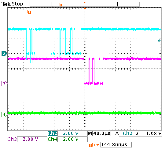
Figure 5. Using a digital oscilloscope (DSO) to monitor RxIN and TxIN, shows that the MAX9258 receives the data transmitted on the link.
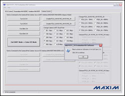
After setting the jumper, the camera control label must close UART mode and enter I²C mode: Click Exit UART Mode-> Enter I²C Mode. In order to work properly in I²C mode, pins 2-3 of JU26 and JU27 must be shorted-follow the instructions in the software pop-up window (Figure 6).
Detailed pictures (PDF)
Figure 6. Screen description when I²C is working properly. When working in I²C mode, make sure that pins 26 and 3 of JU26 and JU27 are equipped with a shunt.
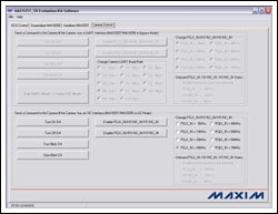
Now, the system has enabled the lower half of the Camera Control page. As shown in Figure 7, the upper part of the page is grayed out, indicating that it works in I²C mode and UART mode is not enabled.
Detailed pictures (PDF)
Figure 7. The upper part of the Camera Control page is grayed out, indicating that I²C mode is enabled.
If you click the button on the left, D4 turns on / off and blinks fast / slowly, which is used to simulate camera control. From this, you can see the control of the I²C operating mode on the camera side. D4 is located in the upper right of the FPGA, close to the microcontroller of the deserializer board.
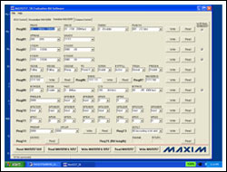
In order for the link to work properly, the SerDes and pixel clock links must be set up. For testing, assume that the SerDes pixel clock rate is 10MHz and the bit resolution is 12 bits (Figures 8 and 9).
Detailed pictures (PDF)
Figure 8. Serializer MAX9257 page after setting all parameters
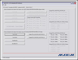
Detailed pictures (PDF)
Figure 9. Camera Control screen after proper setup
Note that the SerDes screen display is similar. For the purpose of this application note, only the serializer setting screen in the camera mode is given. According to the same SerDes screen settings, you can make the system work normally in the camera mode.
This will result in the settings shown in Table 2.
Table 2. SerDes setting results
Before enabling PCLK on the Camera Control page, be sure to write these parameters.
Click the Enable PCLK_IN / HSYNC_IN / VSYNC_IN button on the Camera Control page, as shown in the screen in Figure 10. This screen shows the typical transmission sequence when PCLK is enabled or disabled on the Camera Control page. It is only used for verification and displays the signal status of the data when it is transmitted in I²C mode.
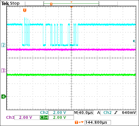
Figure 10. This transfer sequence illustrates the data status in I²C mode after PCLK is enabled.
After setting the deserializer correctly, the result should be as shown in the screen of Figure 11, showing the detailed PRATE, SRATE and PWIDTH. If the TxIN pin is triggered and this information is written to the deserializer, the oscilloscope display result shown in Figure 12 will be obtained. It only displays the transmitted information and does not receive the information.
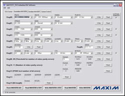
Detailed pictures (PDF)
Figure 11. The MAX9258 deserializer is set correctly
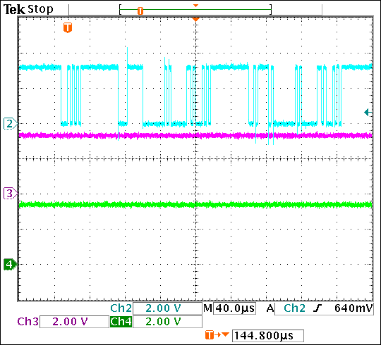
Figure 12. The transmission result of the MAX9258 deserializer displayed on the oscilloscope after the correct setting
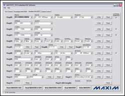
Similarly, setting up the serializer correctly should result in the screen shown in Figure 13, showing detailed PRATE, SRATE, and PWIDTH. Note that to ensure normal communication, the SEREN bit of the serializer should be enabled. Since the I²C mode provides a very flexible interface communication, the SEREN bit can be enabled even in the late setting stage.
Detailed pictures (PDF)
Figure 13. The figure above shows that the MAX9257 serializer is set correctly. The Deserializer MAX9258 screen should be similar to the screen display, so that the system can work normally in camera or I²C mode.
Conclusion Through the introduction of this article, the user can basically operate the display window / bit / register as needed. If the MAX9257 / MAX9258 do not respond, you may need to reset the system. Please note that you need to return to the ECU Control page, click the Reset the EVKIT button, turn off the power, and then turn it on again to wake up the MAX9257 from the remote side again. If it is required to work in I²C mode, start the above process again. Also note that since the circuit board is reset to UART mode, two short-circuiters of JU26 and JU27 need to be set. After processing the limited CTO mode, the UART mode is required to put the MAX9257 / MAX9258 into I²C mode (that is, to set the CTO timing in the CTO register of the serializer and deserializer to 64 bits).
The following content provides an in-depth introduction to all the functional and feature tests of the MAX9257 / MAX9258 evaluation board. As a special example, I²C mode was selected. Before configuring this mode, power on the evaluation board as usual and start the software. This application note assumes that users have mastered and are familiar with the use of the MAX9257 / MAX9258 evaluation board. Note that the MAX9257 / MAX9258 evaluation board information requires an application to obtain it.
Make sure all jumpers are in the default position, as shown in Table 1.
Table 1. MAX9257 / MAX9258 EV kit jumper settings
| JU1 | Shunted | AcTIve-low PD pin is pulled up to VCC by a 1kΩ resistor |
| JU2 | Open | LVDS line-probing connector |
| JU3 | Open | LVDS line-probing connector |
| JU4 | Shunted | AcTIve-low ERROR pin is pulled up to VCCOUT by a 1kΩ resistor |
| JU5 | Shunted | LOCK pin is pulled up to VCCOUT by a 1kΩ resistor |
| JU6 | Shunted | MAX9258 VCC is connected to an on-board LDO + 3.3V output |
| JU7 | Shunted | MAX9258 VCCOUT is connected to an on-board LDO + 3.3V output |
| JU8 | Shunted | MAX9258 VCCPLL is connected to an on-board LDO + 3.3V output |
| JU9 | Shunted | MAX9258 VCCSPLL is connected to an on-board LDO + 3.3V output |
| JU10 | Shunted | MAX9258 VCCLVDS is connected to an on-board LDO + 3.3V output |
| JU11 | Shunt across pins 2-3 | MAX9258 is powered by an on-board LDO (U4), whose input is + 5V |
| JU14 | Shunt across pins 2-3 | LVDS cable line 1 is connected to ground |
| JU15 | Shunted | MAX9258 RX pin is connected to the on-board emulaTIng ECU Rx line |
| JU16 | Shunted | MAX9258 TX pin is connected to the on-board emulaTIng ECU Tx line |
| JU17 | Shunt across pins 2-3 | MAX9257 SCL / TX pin is pulled up to VCCIO |
| JU18 | Shunt across pins 2-3 | MAX9257 SDA / RX pin is pulled up to VCCIO |
| JU19 | Shunted | MAX9257 VCC is connected to an on-board LDO + 3.3V output |
| JU20 | Shunted | MAX9257 VCCIO is connected to an on-board LDO + 3.3V output |
| JU21 | Shunted | MAX9257 VCCFPLL is connected to an on-board LDO + 3.3V output |
| JU22 | Shunted | MAX9257 VCCSPLL is connected to an on-board LDO + 3.3V output |
| JU23 | Shunted | MAX9257 VCCLVDS is connected to an on-board LDO + 3.3V output |
| JU24 | Shunt across pins 2-3 | J6 connector has one side connected to ground |
| JU25 | Shunt across pins 2-3 | MAX9257 REM pin is connected to ground |
| JU26 | Shunt across pins 1-2 | MAX9257 SCL / TX pin is connected to the on-board emulating camera Rx line |
| JU27 | Shunt across pins 1-2 | MAX9257 SDA / RX pin is connected to the on-board emulating camera Tx line |
| JU29 | Shunt across pins 2-3 | LVDS cable line 1 is connected to ground |
| JU30 | Open | LVDS line-probing connector |
| JU31 | Open | LVDS line-probing connector |
Connect a 5V power supply between the 5V and GND pads on both layers of the evaluation board (Figure 1). Do not turn on the power until all connections are completed and all jumpers are correctly positioned.

Figure 1. Configuration settings for experimental testing
Connect the JAE cable between J2 and J7. Connect CH1 of the oscilloscope to J1-37. Connect CH2 of the oscilloscope to J1-35. Connect CH3 of the oscilloscope to J5-12. Connect the USB cable between the PC and J3 (note: not J8). In the Start menu, open its icon to start the MAX9257_58 evaluation software. When the "if ECU remotely wakes up the MAX9257" menu pops up, click the Yes button. The main software window shown in Figure 2 appears.

Detailed pictures (PDF)
Figure 2. The main software window that appears when the Yes button is clicked indicates that the MAX9257 is waked up remotely by the ECU. Once the ECU wakes up the MAX9257, TxIN, RxOUT and CCEN are all high.
Make sure that the "EV kit connected" message is displayed in the status bar of the main window of the software, indicating that the evaluation board is connected correctly. Click the ECU Wakes Up MAX9257 button on the ECU Control page (Figure 3).

Detailed pictures (PDF)
Figure 3. Click the ECU Wakes Up MAX9257 button
Click the Deserializer MAX9258 tab to jump to the Deserializer MAX9258 page (Figure 4).

Detailed pictures (PDF)
Figure 4. Jump to the Deserializer MAX9258 page
Click the Read MAX9258 & 9257 button to read the MAX9258 and MAX9257 registers. Select the ETOCNT drop-down menu and click the Write button to the right of Reg03 to set MAX9258 register 03 ETOCNT and MAX9257 register 03 ETOCNT to 0100. Set the MAX9258 register 07 CTO and MAX9257 register 08 CTO to 111 by selecting the CTO drop-down menu and clicking the Write button to the right of Reg07. Click the Serializer MAX9257 tab to jump to the Serializer MAX9257 page. Select the SEREN pull-down menu and click the Write button to the right of Reg04 to enable the MAX9257 SEREN bit. Note that when there is data communication on the link, the SEREN window should always be active. Click the Camera Control tab to jump to the Camera Control page. Click the Slow Blink D4 button; make sure the LED D4 flashes for about 5 seconds. Click the Enable PCLK_IN / HSYNC_IN / VSYNC_IN button; make sure that the LOCK indicator LED D1 is turned on. If it is on, the system is locked. Use a multi-track oscilloscope to check the board waveform. Set the corresponding trigger, you can observe the link's sending / receiving process and the transmitted data. After verifying the general functionality of the board, you can follow the steps below to put the evaluation board into I²C mode. I²C is a required mode that allows users to maintain control of all control registers and their contents.
If the camera has an I²C interface, both the MAX9258 and MAX9257 should be configured for I²C interface operation. Since the on-board emulated camera works on the default UART interface, the camera should first switch from the UART interface to the I²C interface. Follow the steps below to use the I²C interface of the evaluation board.
Start the program or click the Reset the EVKIT button on the ECU Control page. If MAX9257 REM is set high (JU25 1-2 pins are equipped with a shunt), click the ECU Wakes Up MAX9257 button on the ECU Control page. If MAX9257 REM is set to low level (JU25 2-3 pin is equipped with a shunt), skip this step. Jump to the Deserializer MAX9258 page. Click the Read MAX9258 & 9257 button to refresh the GUI's current register value, and the most recent register value (or the default value at startup) will be displayed. Select the 4 check boxes under the W / R Both 9258 & 9257 label, and the SerDes register can be set at the same time, so that users can avoid contradictions in the SerDes parameter settings. Set the MAX9258 and MAX9257's tCTO to 64 bits (CTO = 100). Jump to the Camera Control page; click the Exit UART Mode-> Enter I²C Mode button. Follow the information prompts-change the short-circuiter from pins 1-2 of JU26 / JU27 to pins 2-3, and click the OK button. Now, the camera and SerDes have adopted I²C interface to work. You can verify that the camera is working properly by testing the on / off and fast / slow blinking of the D4 diode. The control button for this function is located on the left side of the form. You can jump to any page and use this function of SerDes (ie, rewrite to each accessible register). When simulating the I²C interface of a camera, the operating speed is as high as 4.25MHz, as is the MAX9258 and MAX9257. Before changing the ECU I²C master clock, the BITRATE register bits of the MAX9258 and MAX9257 should be correctly configured. If data is transmitted on the link, make sure that SEREN is set to Enabled. Test instruments and components required to verify the performance of the MAX9257 / MAX9258 evaluation board Hewlett-Packard E3620A: dual 0 to 25V, 0 to 1A power supply. Tektronix TDS 3014: 4-channel DSO, 100MHz BW, 1.25Gsps sampling rate and standard 10x probe. PC or laptop based on Windows® XP, supports USB interface. 2m JAE cable (effective connection between the MAX9257 serializer and MAX9258 deserializer) I²C communication mode of the MAX9257 / MAX9258 evaluation board This test procedure describes the steps for the evaluation board to communicate in I²C mode. For this mode to work properly or set correctly, the system must first be started in UART interface mode. Setting MAX9257 / MAX9258 requires software to set INTMODE = I²C (make sure to check the option box on the right side of the screen to update / write to MAX9257 and MAX9258). To write to the device, trigger the TxIN pin once to collect the command sequence written to the device (ie, to establish the I²C mode setting). The board shown in Figure 5 is configured to send (TxIN, CH2) and receive (RxIN, CH3) data in the limited CTO mode, which is required when configuring the board for I²C mode. Note that all steps are performed in UART mode (JU26 and JU27 pins 1-2 are equipped with a shunt).

Figure 5. Using a digital oscilloscope (DSO) to monitor RxIN and TxIN, shows that the MAX9258 receives the data transmitted on the link.
After setting the jumper, the camera control label must close UART mode and enter I²C mode: Click Exit UART Mode-> Enter I²C Mode. In order to work properly in I²C mode, pins 2-3 of JU26 and JU27 must be shorted-follow the instructions in the software pop-up window (Figure 6).

Detailed pictures (PDF)
Figure 6. Screen description when I²C is working properly. When working in I²C mode, make sure that pins 26 and 3 of JU26 and JU27 are equipped with a shunt.
Now, the system has enabled the lower half of the Camera Control page. As shown in Figure 7, the upper part of the page is grayed out, indicating that it works in I²C mode and UART mode is not enabled.

Detailed pictures (PDF)
Figure 7. The upper part of the Camera Control page is grayed out, indicating that I²C mode is enabled.
If you click the button on the left, D4 turns on / off and blinks fast / slowly, which is used to simulate camera control. From this, you can see the control of the I²C operating mode on the camera side. D4 is located in the upper right of the FPGA, close to the microcontroller of the deserializer board.
In order for the link to work properly, the SerDes and pixel clock links must be set up. For testing, assume that the SerDes pixel clock rate is 10MHz and the bit resolution is 12 bits (Figures 8 and 9).

Detailed pictures (PDF)
Figure 8. Serializer MAX9257 page after setting all parameters

Detailed pictures (PDF)
Figure 9. Camera Control screen after proper setup
Note that the SerDes screen display is similar. For the purpose of this application note, only the serializer setting screen in the camera mode is given. According to the same SerDes screen settings, you can make the system work normally in the camera mode.
This will result in the settings shown in Table 2.
Table 2. SerDes setting results
| Page Designator | Signal | Setting |
| Camera Control | PCLK_IN | 10MHz |
| SerDes Control | PRATE | 00 (5MHz to 10MHz) |
| SRATE | 01 (100Mbps to 200Mbps) | |
| PWIDTH | 001 (12 bits) |
Before enabling PCLK on the Camera Control page, be sure to write these parameters.
Click the Enable PCLK_IN / HSYNC_IN / VSYNC_IN button on the Camera Control page, as shown in the screen in Figure 10. This screen shows the typical transmission sequence when PCLK is enabled or disabled on the Camera Control page. It is only used for verification and displays the signal status of the data when it is transmitted in I²C mode.

Figure 10. This transfer sequence illustrates the data status in I²C mode after PCLK is enabled.
After setting the deserializer correctly, the result should be as shown in the screen of Figure 11, showing the detailed PRATE, SRATE and PWIDTH. If the TxIN pin is triggered and this information is written to the deserializer, the oscilloscope display result shown in Figure 12 will be obtained. It only displays the transmitted information and does not receive the information.

Detailed pictures (PDF)
Figure 11. The MAX9258 deserializer is set correctly

Figure 12. The transmission result of the MAX9258 deserializer displayed on the oscilloscope after the correct setting
Similarly, setting up the serializer correctly should result in the screen shown in Figure 13, showing detailed PRATE, SRATE, and PWIDTH. Note that to ensure normal communication, the SEREN bit of the serializer should be enabled. Since the I²C mode provides a very flexible interface communication, the SEREN bit can be enabled even in the late setting stage.

Detailed pictures (PDF)
Figure 13. The figure above shows that the MAX9257 serializer is set correctly. The Deserializer MAX9258 screen should be similar to the screen display, so that the system can work normally in camera or I²C mode.
Conclusion Through the introduction of this article, the user can basically operate the display window / bit / register as needed. If the MAX9257 / MAX9258 do not respond, you may need to reset the system. Please note that you need to return to the ECU Control page, click the Reset the EVKIT button, turn off the power, and then turn it on again to wake up the MAX9257 from the remote side again. If it is required to work in I²C mode, start the above process again. Also note that since the circuit board is reset to UART mode, two short-circuiters of JU26 and JU27 need to be set. After processing the limited CTO mode, the UART mode is required to put the MAX9257 / MAX9258 into I²C mode (that is, to set the CTO timing in the CTO register of the serializer and deserializer to 64 bits).
Other capacitors
Other Capacitors,Ac Filter Capacitor,Power Saver Capacitor,Line Filter Capacitor,Low Voltage Capacitor
YANGZHOU POSITIONING TECH CO., LTD. , https://www.cnchipmicro.com