In an embedded system, the BootLoader is used to initialize the hardware, load the kernel, and pass parameters. Because the hardware environment of the embedded system is different, the BootLoader of the embedded system is also different. The more common one is U-Boot, which supports different architectures such as ARM, PowerPC, X86, MIPS, etc. This article focuses on the basic functions of parameter passing between BootLoader and the kernel. The hardware platform of this paper is based on the AT91RM9200 processor system, and the software platform is the Linux-2.6.19.2 kernel. The kernel image file is zImage.
1. Introduction to the system hardware platformAT91RM9200 processor, which is based on Atmel's ARM920T core-based microprocessor with memory management unit and CPU clock up to 240MHz. It has a rich standard interface, EBI interface, and integrated static memory controller (SMC). , SDRAM controller, BurST Flash controller. Refer to the AT91RM9200 data sheet for a description of the processor. The address of the system SDRAM (64MB) is: 0x20000000, and the address of NorFlash (8MB) is: 0x10000000[1].
2. BootLoader design and implementationThe documentaTION/arm/booTIng[2] document under the kernel source tree specifies the basic functionality of the ARM architecture based on the BootLoader. In addition to these basic functions, the BootLoader of this system also incorporates functions such as code handling in combination with the characteristics of its own hardware.
The process of the BootLoader is: after the system power-on reset, it starts running from NorFlash (determined by the processor BMS pin connection), because the 0 address of the processor is the first address of NorFlash (0x10000000), and the BootLoader is programmed. In this position, the address range that the AT91RM9200 processor can map is only 0x0000.
0000—0x001f ffff. The first step in the BootLoader execution is to transfer its own code from NorFlash to the internal RAM of the processor (0x00200000), then map the 0 address to the internal RAM and jump to the corresponding address in the internal RAM to continue execution. After entering the internal RAM, it enters the real hardware initialization phase. The various controllers initialized at this stage are required by the kernel, including: PMC, EBI, SMC, SDRAM, USART, etc. The next step is to create a Tagged list. The created linked list is to transfer the kernel image and root file system image previously written in NorFlash to SDRAM. The interrupt, MMU and data cache are closed according to the basic requirements of the kernel for the BootLoader. R0=0, r1=0x0000 00fb or 0x00000106 (according to the kernel linux/arch/arm/tools/mach-types[2]
The specified machine number), r2=0x20000100 (the physical address that the BootLoader passes to the kernel parameter list). In the ARM architecture, this address is the default in the machine descriptor (machine_desc) of the same processor, so here Can not be specified. Finally, the BootLoader jumps directly to the core of the SDRAM for execution.
3. Kernel parameter listThe BootLoader can pass parameters to the kernel in two ways. One is the old parameter structure (parameter_struct), which is mainly used by the kernel before 2.6. The other is the tagged list method used by the current 2.6 kernel. These parameters mainly include the system's root device flag, page size, memory start address and size, RAMDISK start address and size, compressed RAMDISK root file system start address and size, kernel command parameters, etc. [3] [4] [5].
The format and description of the kernel parameter list can be found in include/asm-arm/setup.h[2] in the kernel source tree. The parameter list must start with ATAG_CORE and end with ATAG_NONE. Here ATAG_CORE, ATAG_NONE is the tag of each parameter, itself is a 32-bit value, for example: ATAG_CORE=0x54410001.
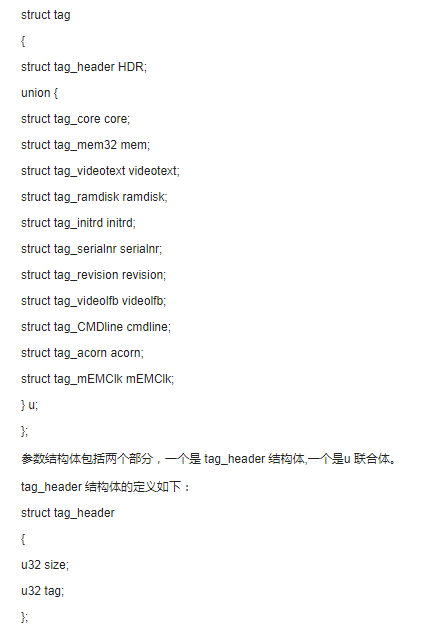
Other parameter markers include: ATAG_MEM32, ATAG_INITRD, ATAG_RAMDISK, ATAG_COMDLINE, and so on. Each parameter marker represents a parameter structure, and each parameter structure constitutes a parameter list. The definition of the parameter structure is as follows:

Where size: indicates the size of the entire tag structure (in terms of the number of words, not the number of bytes), equal to the size of the tag_header plus the size of the u union, for example, the parameter structure ATAG_CORE
Size=(sizeof(tag->tag_header)+sizeof(tag->u.core))>>2, generally obtain the size of each parameter structure by the function tag_size(struct * tag_xxx). Tag: indicates the tag of the entire tag structure, such as: ATAG_CORE.
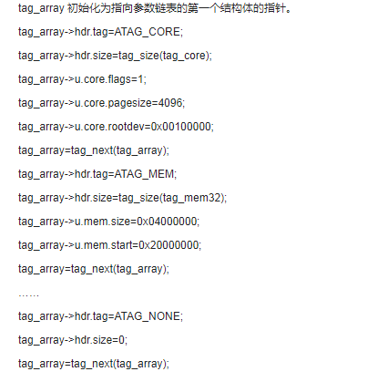
Consortium u includes all selectable kernel parameter types, including: tag_core, tag_mem32, tag_ramdisk, and so on. The traversal between the parameter structures is implemented by the function tag_next(struct * tag). The system parameter list includes the following structures: ATAG_CORE, ATAG_MEM, ATAG_RAMDISK, ATAG_INITRD32, ATAG_CMDLINE, ATAG_END. Except for the fixed position of the parameter structures ATAG_CORE and ATAG_END in the entire parameter list, the order of other parameter structures is arbitrary. The parameter list passed by this BootLoader is as follows: the first kernel parameter structure, labeled ATAG_CORE, and the parameter type is tag_core. Please refer to the source code file for the definition of each parameter type. 
Finally, copy the kernel parameter list to the kernel's default physical address 0x20000100. This parameter list is built.
4. Kernel receive parameters
The following is an analysis of the zImage image based on the ARM architecture to analyze how the Linux kernel receives the kernel parameters passed by the BootLoader.
In the file arch/arm/boot/compressed/head.S[2] start is the starting point of zImage, part of the code is as follows:
Start:
Mov r7, r1
Mov r8, r2
......
Mov r0, r4
Mov r3, r7
Bl decompress_kernel
b call_kernel
Call_kernel:
......
Mov r0, #0
Mov r1, r7
Mov r2, r8
Mov pc, r4
Piezoelectric ceramic are a ferroelectric compound. This means, that the electro-mechanical conversion process for producing a motion is related a kind of self-enhancement process based on an internal reorganization of the material's structure. This self-enhancement process results in the higher piezoelectrical efficiency of PZT when compared to natural materials like quartz.
Piezoelectric ceramic are generally manufactured from PZT (Pb - lead, Zr - zirconium, Ti - titanium). The PZT- formulation can be varied with a variety of dopants allowing for a broad spectrum of material properties optimized for different application profiles.
Yuhai Company is able to manufacture piezoelectric ceramic elements in a wide range of shapes and sizes. piezoelectric discs, piezo rings, piezo plates, and piezo tubes (cylinders) is the main shapes Yuhai Company most frequently manufactures, we also have a great deal of experience manufacturing hemispheres, trapezoids and other customized shapes.
If the listed shapes and sizes was not the elements you are looking for, please contact us for more information. We can work with you to create the correct shape and size for you.Piezoelectric Elements,Piezo Ceramic Disc,Piezoelectric Ceramic Discs,Pzt Element
Zibo Yuhai Electronic Ceramic Co., Ltd. , https://www.yhpiezo.com