1 Introduction
In the construction of highways in mountainous areas, the proportion of tunnels is very large. The cost of using road tunnels after completion of traffic is quite alarming. Due to the underdeveloped economy in remote mountainous areas and the small traffic volume, the tunnel lighting costs have become a heavy burden for the highway tunnel management department. Especially in the first few years of operation, the tolls collected are not enough to operate maintenance expenses. How to improve the operational efficiency of tunnels and reduce energy consumption has become an urgent problem to be solved in highway construction.
Most of the existing tunnel lighting control adopts the timing control method, which mainly achieves the purpose of increasing or decreasing the number of working lamps by reversing different lighting circuits. Although this control method is simple and reliable, it does not fully consider the influence of environmental factors on tunnel lighting, such as weather conditions, tunnel ventilation conditions, traffic volume and vehicle speed control requirements, etc., which cannot fully meet the requirements of tunnel lighting and energy consumption. high. With the rapid development of semiconductor lighting technology, LED lighting lamps with high efficiency and energy saving have been increasingly used in tunnel lighting systems. Compared with the traditional light source, LED has the advantages of low voltage, low power consumption, high reliability and long life. It is an environmentally friendly and energy-saving green lighting source. In order to further develop the technical and economic advantages of LED lighting, when using LED as the tunnel lighting, it should pay attention to optimize the lighting design lighting scheme according to the actual situation, and improve the control strategy and control means. The driving power of the LED lamp can accept the dimming control signal, and the output current is controlled to control the light output of the LED lamp. This feature allows us to reduce the lighting energy consumption and improve the technical level of the system by adopting more sophisticated control technology. This paper will propose the realization and application of LED tunnel lighting control system from the perspective of perfect control strategy, comprehensively analyze the requirements and characteristics of tunnel lighting, and provide a complete solution for high-power LED tunnel lighting control system.
2 system architecture design
The LED tunnel lighting control system is mainly composed of the main control computer of the monitoring center, the on-site LED tunnel lighting controller and related communication equipment. The tunnel lighting controller collects the external illumination value of the tunnel, the illumination value in the tunnel, the traffic volume, the vehicle speed and other values ​​through the on-site sensor, and uploads the data to the monitoring center. The main control computer calculates the current illuminance parameters of each tunnel and each section according to the prescribed dimming control logic, and then issues a dimming control command to each tunnel LED lighting controller through the communication network. According to the characteristics of the tunnel, the tunnel lighting control includes the entrance section area lighting control, the transition section area lighting control, the basic section area lighting control (several) and the exit area lighting control. The tunnel lighting controller automatically adjusts the output current of the lamp power supply (the duty ratio of the PWM mode) according to the received adjustment command, and changes the luminous flux or working state of the LED tunnel light. The main control computer detects the illumination of the current tunnel illumination in real time through the illumination sensor, and determines whether the current illumination meets the tunnel illumination requirements. If not, the new control command is issued to the LED tunnel light, thereby changing the illumination of the tunnel. Data transmission between the luminaire and the lighting controller, as well as between the luminaire and the luminaire, can be connected by fieldbus. In order to meet the actual control needs of the site, the tunnel lighting controller is equipped with multiple output interfaces, which can control up to 8 outputs at the same time. In order to ensure the safety of driving, the dimming system uses the illuminance gradient control method to adjust the illumination of the tunnel to achieve the target illumination step by step to avoid unsafe factors due to sudden changes in illumination.
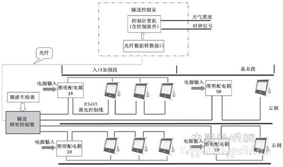
The structure of the LED tunnel lighting control system is shown in Figure 1.
As shown in FIG. 1 , the tunnel lighting controller collects detection signals of sensors such as a vehicle detector and an illuminance detector, and controls the illumination system of the entire tunnel according to a preset lighting control strategy. The control strategy of the system is as follows: Under normal circumstances, when no vehicle enters the tunnel, according to the detected difference between the external and external illumination of the hole, only the corresponding basic illumination is turned on in the tunnel; when the vehicle detector detects that the vehicle is about to enter the tunnel, it is turned on. Enhanced lighting of the tunnel entrance; when the vehicle is detected to enter the tunnel, the illumination of the corresponding distance in front of the vehicle is strengthened; once no vehicle follow-up is detected, the enhanced illumination behind the vehicle is turned off, and the basic illumination illumination is lowered. At the same time, according to the detected illuminance value, it is also possible to judge the data of the sunny day, the cloudy day, the daytime, the evening, and the like, thereby turning on or off the corresponding lighting fixture.

Figure 1 Schematic diagram of LED tunnel lighting control system
The system can perform single control for individual lighting or group control for regional lighting. The control strategy can be corrected at any time according to actual conditions, which can save a lot of power and effectively reduce operating costs. In addition, according to the security requirements of the tunnel, in the event of a fire, the system can also detect the condition of the rolling door and ventilation of the cross-hole in the tunnel.
3 system communication network design
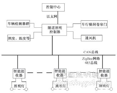
The topology of the LED tunnel lighting control system is shown in Figure 2.

Figure 2 Schematic diagram of system network topology
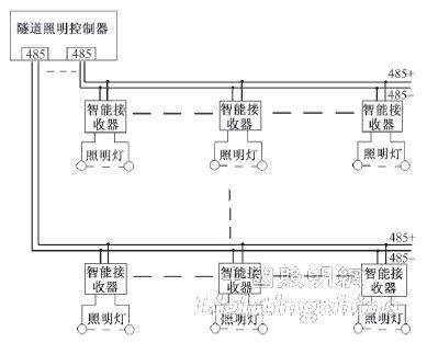
If the interface of the LED light intelligent receiving controller is RS485 bus type, the RS485 module of the tunnel lighting controller can be used, and the system wiring is as shown in Fig. 3.

Figure 3 RS485 bus lighting control schematic
The wiring of the CAN bus and the RS485 bus are similar. The CAN bus has a complete communication protocol and is faster than RS485, and the nodes in the CAN network have an automatic shutdown output function in case of a serious error, so that the operations of other nodes on the bus are not affected.